SensorAktor-Shield
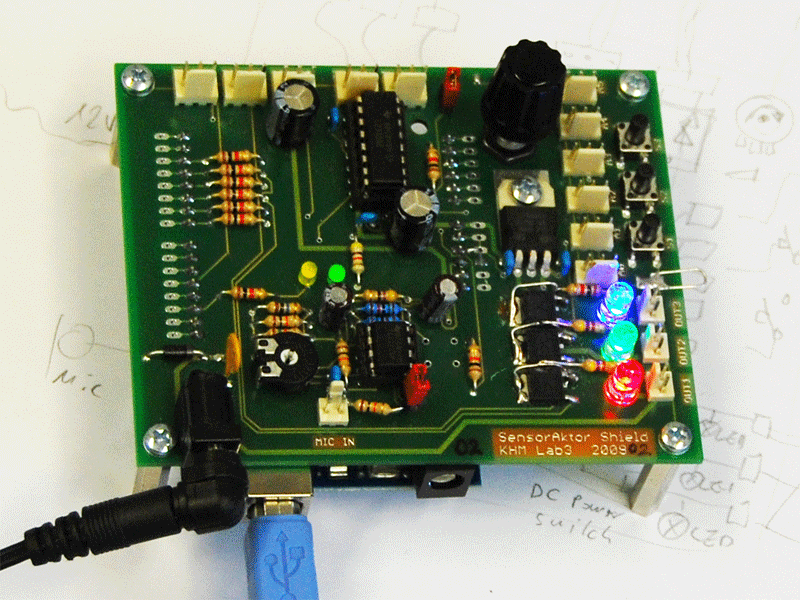
The SensorAktor-Shield is an extension for the Arduino Board that allows to get quick into the world of sensors and aktuators. (like Motors Solenoids, Servos etc.) The goal was to extend the Arduinos input and output capabilities by some functional blocks like power switches and amplifiers that allows the direct connection of power consuming devices like DC-Motors, Stepper Motors, Solenoid Magnets, Halogen Lamps etc. or various sensor devices. Instead of adding those functional blocks by breadboarding additional electronic circuits this board offers those capabilities for the most common techniques. This avoids a tangle of cables and wires around the Arduino board which would discourage the beginner and might lead to the destruction of the Arduino board. So numerous experiments can be done by simply connecting these sensors or aktuator to the header connectors provided on the SensorAktor-Shield.
Attaching The Arduino to the SensorAktor-Shield
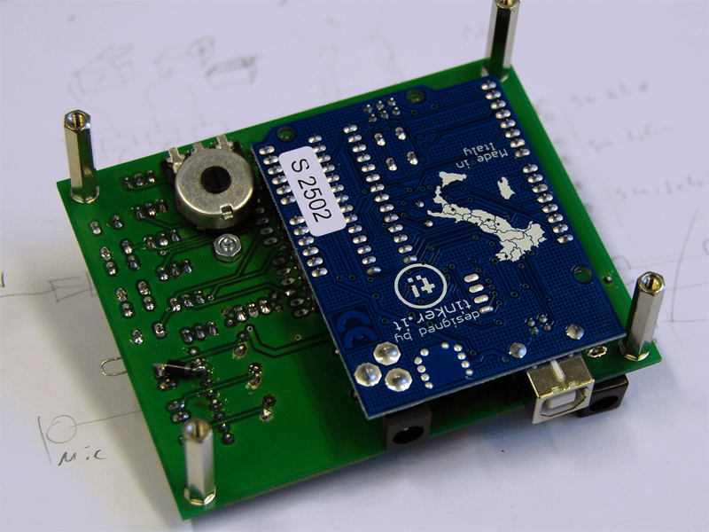
Flip the Shield over to the top and locate the to rows of pin headers on the board. Now gently plug in the Arduino onto the Shield.
Two drillholes on the shield allowing the Arduino to be fasten additionally with plastic screws if required.
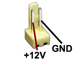
Now connect the USB cable and the 12Volt DC power adaptor to the jack on the Shield. (Plug Tip is + pole)
When the green LED on the shield lights up everything is OK and you are ready to upload you first programm.
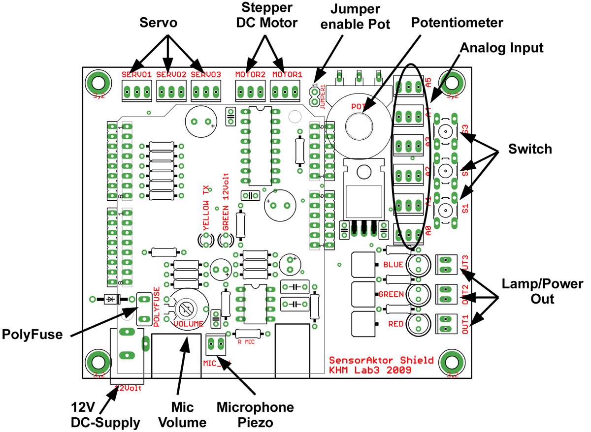
Board Placeplan
The Fuse
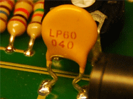
Next to the power jack on the shield you see a little yellow disk which is a Polyfuse to protect all circuits form overcharging in the case you made anything wrong. The green LED indicates a correct 12 Volt power status. If the LED isn’t on anymore a fault is present and the fuse is probably activated. After disconnecting the power supply the Polyfuse resets after about 30 seconds and the board should work normally again.
Header Connectors for Servos and analog Sensors
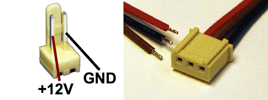
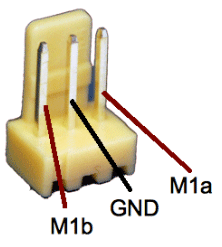
All connections to the peripheral devices are made with 2 or 3 way crimp connectors to get a save connection. Pre assembled plugs with cables allowing to be quickly soldered to a sensor or a motor .
With the three Servo connectors you are able to attach standard RC-Servos to the Board. The Shield provides an extra power regulator on board to supply the servos with a voltage of 5 Volt and enough current to get sufficient mechanical torque out of the servos.
When the servos are not used these connectors can be uses as general purpose digital in or output.
The six analog inputs for sensors A0..A5 have the same connection scheme like the servo connectors. The Signal pin accepts a input voltage between 0 and 5 volts to be measured by the Arduinos analogInput function. Ground and +5V can be used as a supply voltage for active sensors or as reference voltage for if you use simple resistive sensors.
Be sure not to plug in a sensor onto the motor connectors !
The Stepper and DC-Motor Connectors
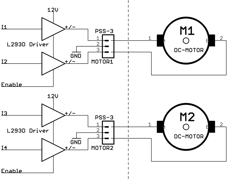
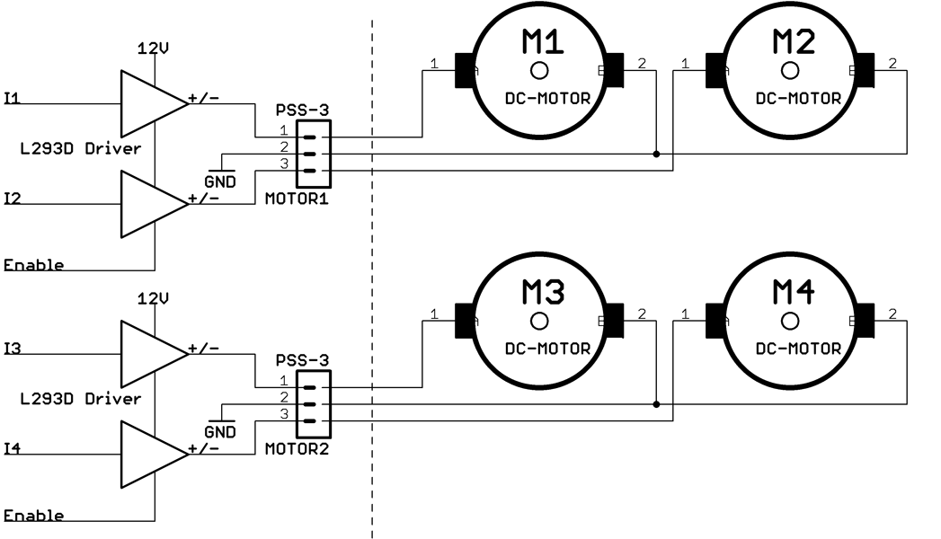
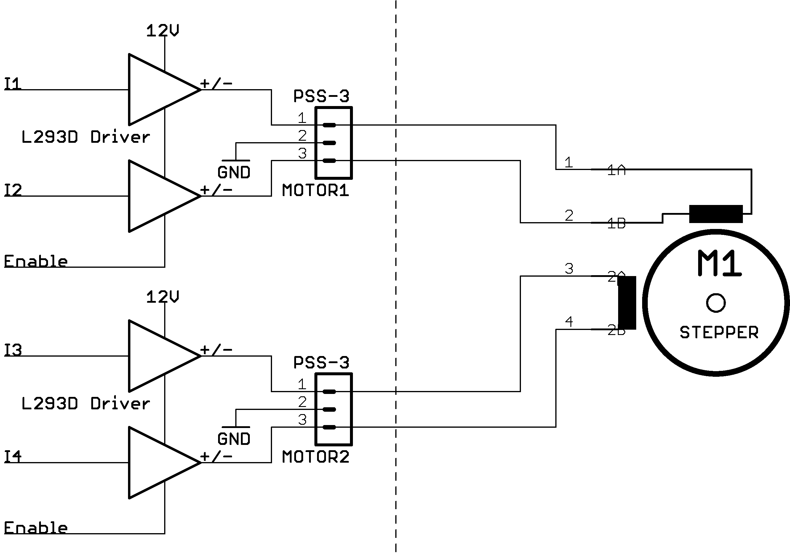
There are various schemes how DC-Motors and Steppers can be connected to the Header Motor1 and Motor2. It is possible to have one Stepper Motor, 2 DC-Motors running in both directions or 4 DC-Motors running in one direction.
Motor Connection Schemes
The motors are connected to an L293 motor driver chip on the board. This circuit has four output stages which can be set to 12V or Ground depending on the level of the four input lines I1 .. I4. When the motors are between two driver stages the voltage to the motors can be reversed so that they can run in both directions. The enable line can be used to contraol the power of the motor by PWM.
Four motors on can be controlled but the running direction can’t be reversed.
A four phase bipolar Stepper motor must be connected a all four driver stages. The L293 Stepper library takes care of the right switching pattern and controls the motor tourqe by PWM.
Out Connectors
The three Out connectors can switch various loads like Lamps, Solenoids etc. It’s a low-side switch so that, when switched on, the GND pin is on the minus of the 12V power supply. The +12V is fixed on the + of the power supply.
The Potentiometer
The Potentiometer on the board is connected to analogInput 5 an delivers a voltage for 0 to 5 Volt depending on the wiper position. When you use the A5 connector as a sensor input you have to remove the enable Pot. Jumper because otherwise A5 and Pot are running parallel.
Switches
The Switches S1..S3 are hooked to the analog Inputs A1..A3. They should not used when these inputs are utilized by sensors.
Since they are on analog inputs look at the program examples how to read their state.
Microphone Input
The Mic Input has an high impedance preamplifiers to accommodate simple piezo disks as, for instance, force or knock sensors. Also electret Microphone capsule can be used when the resistor R8 is soldered to the board. When the input is quiet you will read on the analogInput 0 an value of about 400 as DC offset. Any input signal will vary this value. The Trimpot PT1 is used to vary the mic volume respectively the amplifier gain.
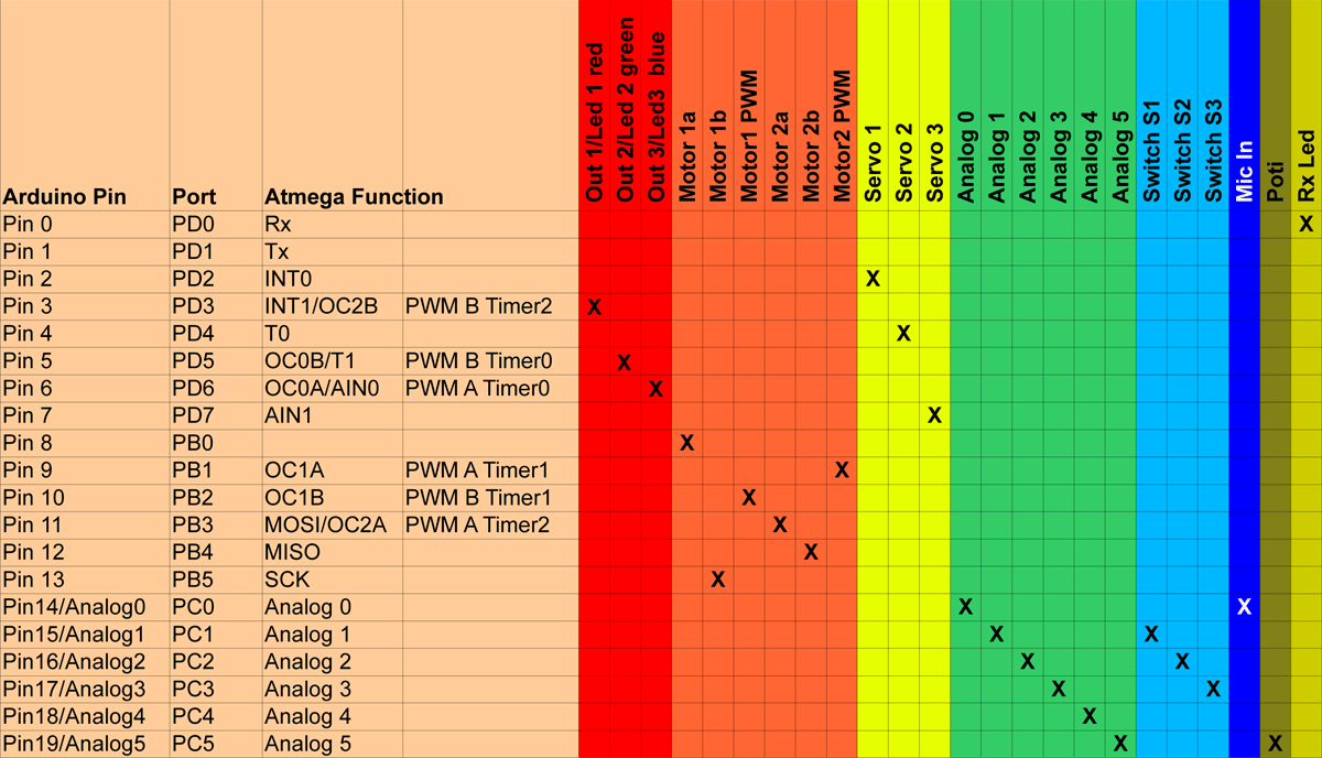
Pin Mapping
Bill of Materials
SensorAktor-Shield schematic
Library
Contact
Martin Nawrath, nawrath@khm.de


