Long Term Time-Lapse Photography
with Arduino and CHDK
Long term time-lapse photography with digital cameras can be done in various ways for instance with a PC controlling a camera by software. Cameras that are allowing to be scripted like the canon cameras are offering many features we are taking advantage of here. A little extra hardware was required to run the camera unattended at a remote place for the timespan of one year.
For our project we had to build a autonomous unit that allows to shoot a HDR picture once a day over a period of one year. The energy consumption had to be optimized to run the setup with one set of batteries over the whole period without any maintenance.
How it works
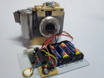
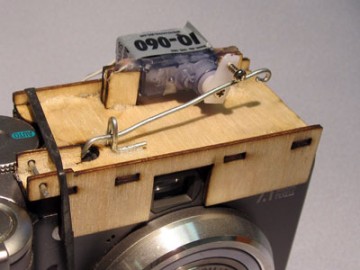
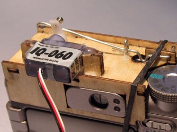
To a little micro controller board, in our case an Arduino, breadboarded realtime clock is attached and delivers a precise time reference. In the code of the Arduino a list keeps all the times when a photo has to be shot, so you can get catch certain events like astronomical occurrences. When the controller wants to shoot a photo a tiny RC-Servo switches the camera on with a “mousetrap” like mechanism then a CHDK script is started automatically and makes a series of photos (bracketing). When the script is finished the last command retracts the lens and switches the camera of to save battery power. To minimize power consumption the controller is in a sleep mode most of the time and checks only every eight seconds if a event is in time. This allows to run the setup over the period of one year.
The “Mousetrap” Mechanism
When Servo arm is turned by 90 degree it presses down the wire lever. A little bow in the wire hits the cameras “on” button. The flexibility of the wire softens the whole thing not to damage the button. The “Mousetrap” itself was build out of 1.5 mm plywood which is easy to cut. The pieces were put together with superglue.
The CHDK Script
This script was put together out of several programs found in the CHDK forum. You will find there further information when you are looking for HDR bracketing.
@title TimeLaps HDR

print "**** Auto Sonnenbilder Reihe ****"

@title Blitz aus
get_prop 16 f
if f = 2 then goto "nof"
print " Flash Off"
set_prop 16 2

:nof
sleep 1000

@title Bracketing
@param a ev range
@default a 3
@param b Num of pictures
@default b 5
@param c Startdelay (in sec)
@default c 0

if a<1 then a=3
if b<1 then b=5
if c<0 then c=0

if c>0 then print "Wait", c, "sec"
sleep c*1000

get_prop 25 x
y=-(a*b-a)*16
z=y/32/3
if z<0 then t=-1 else t=1
set_prop 25 y
set_prop 26 y

shoot
for s=2 to b
  y=y+a*32
  z=y/32/3
  if z<0 then t=-1 else t=1
  set_prop 25 y
  set_prop 26 y
  print "Pic#",s,"of",b,"+",z","(y*10/32/3-z*10)*t,"EV"
  shoot
next s
set_prop 25 x
set_prop 26 x

sleep 1000

shut_down
print "shutdown now, retract lense"

sleep 2000

end
.
Electronics
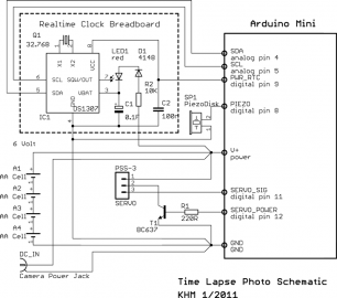
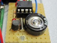
In our case we used our own home made Arduino Clone but a board like the Arduino Mini will do the job also. The schematic shows how to connect all the components the DS1307 is soldered on a little PCB breadboard.
Partlist:
IC: DS1307, Transistor: BC637, Resistor: 10K , 220 Ohm Capacitor: 0.1 F GoldCap, 100n ceramic,Buzzer: Piezo Element 20mm dia., Led: 3mm red, Diode: 1N4158, Crystal: 32.768KHz TC38 Cl:12pF, Servo: Hype IQ60, Camera DC power jack.DS1307
realtime clock breadboard
Arduino Software
The control program is based on our “sleep watchdog example”. The software reads the DS1307 realtime clock chip and compares the actual time to the entrys stored in the program memory. This timetable is found in the TimeTable.h include file where you can edit all the entrys. The total number of entrys is set by the variable “numEntr” and must fit to your table. With a ATMEGA168 chip you have space for around 700 entries otherwise the newer ATMEA328 is required. When starting the program your have the chance to set the realtime clock with a command line in the terminal window. The additional libraries DS1307 and SoftwareServo can be found in the Arduino playground pages. All the other include files are fixed components of the Arduino system. When the programm is running it reads the actual time and date and compares it with the time/date data in the timetable. When the time is equal the servo is moved forth and back by 90 degrees to actuate the cameras “on” button. Otherwise the program forces the processor to fall back in the sleep mode. After eight seconds the hardware watchdog wakes up the processor and the time check is executed again. In our example the data in the timetable are sunrise and sunset times for our geographical position precalculated for one year.
Download TimeLapsePhotoZip project file
Calculating the battery lifetime
The question is how long would last our batteries? Looking through the datasheets of different manufacturers I found a average value of about 2500 mAh capacity for a standard alkaline AA / LR6 cell. When the camera is active (display switched off) I measured 400 mA average current consumption while shooting pictures. So we yield 2500/400 = 6.25 hours or 375 minutes total operating time. Since our camera on switched on for maximum one minute a day the batteries would last one year. A calculation spreadsheet is part of the zip file.
Contact
Martin Nawrath KHM 01/2011, nawrath@khm.de


