Radio Signal Strength Sensor
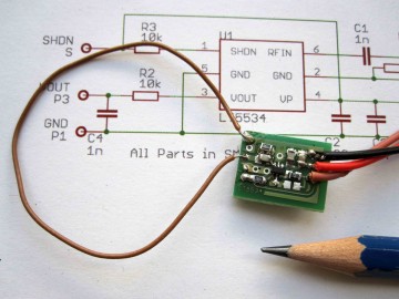
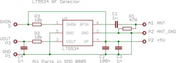
This Sensor is used to detect any Radio Signals in the frequency Range of 50 MHz to 3 GHz (RF Sniffer). With a simple loop Antenna connected to the board you will be able to catch Bluetooth, WLAN, Cellphone Signals in a building. A Cellphone should be detected in a range of about 50 meters. The Sensor is based on a LT5534 Chip from Linear Technology. For further information please refer the PDF document.
The Sensor chip itself is a broadband device which only detects the strenghts of any incoming signal. So you will get no direct information what kind of signal and what frequency you actually receive .
If you connect the output of the board to the audio input of an speaker amplifier you will hear the modulation of the received signal. Due to the different transmission methods you will be able do distinguish Bluetooth, WLAN, Cellphone and TV Signals. For example if you hear a pulses with a frequency of about 200 Hz you received the signals of a GSM Cellphone.
The Antenna is a simple wire loop soldered between input and ground of the sensor PCB.
The loop wire length respectively the loop circumference has influence to the optimal reception of a frequency so you will get a certain selectivity for a desired frequency range.
Antenna Wire Loop Length:
2.4 GHz = 12.5 cm / Bluetooth, WLAN
1800MHz = 16 cm / E Netz GSM
900MHz = 33 cm / D Netz GSM
500 MHz = 60 cm / DVBT K24 Television
100 MHz = 150 cm / FM Broadcast
When using with an Arduino board you have to connect the sensor-output to an analog input. The measured sensor voltage is equivalent to the received radio signal strength. The 5 Volt to power the sensor can be obtained from the Arduino 5V terminal.
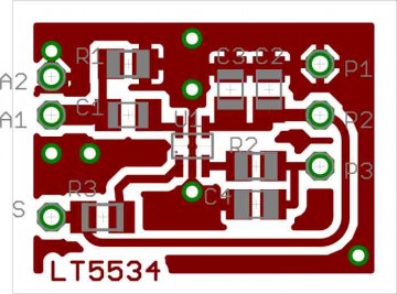
When you plan to built a sensor board yourself please keep in mind that some experience in handling SMD components is required. The lt5534 is very small !
/* LT5534 RSSI Sensor test
 * Lab3 2010
 * Kunsthochschule fuer Medien Koeln
 * Academy of Media Arts Cologne
 * http://interface.khm.de
 */

int analogIn = 0;
int analogValue = 0;
int pinLed = 13;
int cnt;

void setup(){
  Serial.begin(57600);
  pinMode(pinLed,OUTPUT);

}

void loop(){

  analogValue=0;
  for (cnt=0;cnt< 100;cnt++) {
    digitalWrite(pinLed,1);
    analogIn=analogRead(1);
    digitalWrite(pinLed,0);
    if (analogIn > analogValue) analogValue=analogIn;
    delayMicroseconds(100);

  }
  Serial.println(analogValue);
  delay(100);

}
Eagle PCB Layout Files:
Schematic: lt5534_rfssi3
Board : lt5534_rfssi3
GSM sniffer
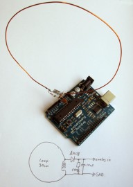
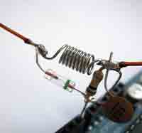
A far more simple circuit acts as a GSM sniffer with a range up to a couple of meters. The Diode is a germanium type AA118, the coil is made of a wire wound ten times over a small screwdriver. The loop wire length is about 33 cm. As program you can try the code as before.
Parts: diode AA118, resistor 100K, ceramic capacitor 10nF, 40cm copper wire
Link:
Martin Nawrath
KHM / March 2010


