Input Channel Extender
24/48/72 Channel Analog Input Extender ( Analog Multiplexer)
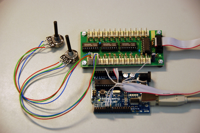
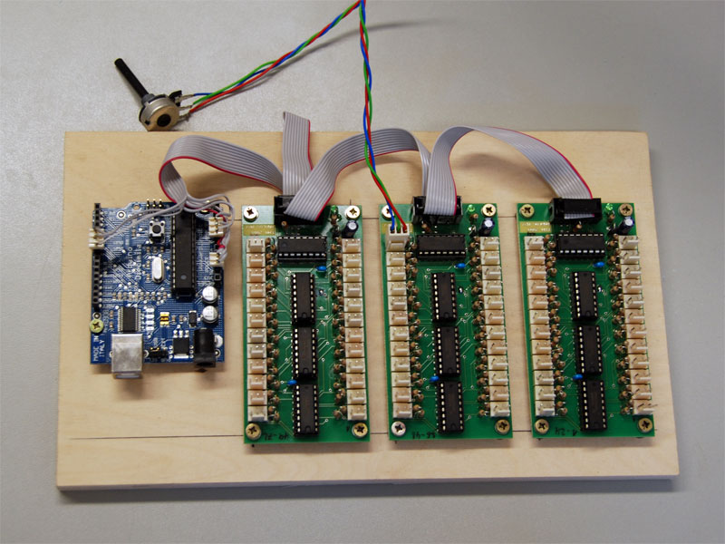
The often demanded request for having more inputs on the Arduino board led to the design of this input extender. With three of these boards cascaded you are able to connect 72 input sources, analog or digital.
If you wish to obtain this board you can send the Eagle Layoutfile to your next PCB manufacturer.
The AMPX_V2.brd is the file of a single board, the AMPX_V2_euro.brd is in 100x160mm euro format with three multiplexer on it.
Most of the PCB manufacturers offer a prototype euro board for about 50 Euro, so you get three multiplexers for a fair price. All the components are standard parts available in every electronic store.
How It Works
The Multiplexer is working similar to an 24 tap rotary switch. The position of the switch wiper is controlled digital by the software.
Three digital ports are used to control the switch position address. The switch position is send serially by the Arduino into a 74HC594 shift register on the board. Three analog 8 to 1 multiplexer ICs CD4051 or 74HC4051 are providing the switching function. The 24 100K Resistors next to the input connectors are optional and can be used when a connected sensor needs an pullup resistor.
The solder bridge SJ1 has to be closed with a drop of solder.
Software
// Analogmultiplexer , 24 Analogeingaege
// KHM 2008
// Martin Nawrath

int ad_1[24];

//Pin Analog 0 connected to Ain pin 6 of Connector SV1

int sr_dataPin = 5;      //Pin 5 connected to SDATA  pin 5 of Connector SV1
int sr_clockPin = 6;     //Pin 6 connected to SCLK   pin 7 of Connector SV1
int sr_latchPin = 7;     //Pin 7 connected to SLATCH pin 9 of Connector SV1
int pinLed = 8;

int led;

void setup(){
  pinMode(sr_latchPin, OUTPUT);
  pinMode(sr_clockPin, OUTPUT);
  pinMode(sr_dataPin, OUTPUT);
  pinMode(pinLed, OUTPUT);

  Serial.begin(57600);
  Serial.println("Analog Multiplexe");
}

void loop() {
  delay (100);
  readMpx(ad_1,0);

  Serial.println("");
  for (int i=0; i < 12 ;i++) {
    Serial.print(i+1);
    Serial.print(":");
    Serial.print(ad_1[i]);
    Serial.print("  ");
    Serial.print(i+13);
    Serial.print(":");
    Serial.println(ad_1[i+12]);
  }
  Serial.print(" ");
}
//****************************************************************
// read analog multiplexer board

void readMpx(int aa[], int ain) {
  int adr;
  int ww;

  led = !led; // led Blink

  for (int cnt=0; cnt < 24 ; cnt++) {
    adr= cnt;                                        // address calculation for the 3 multiplexers
    adr= adr & 7;                                    // on board ( A B A and INH 0 .. 2)
    if (cnt <= 7 ) adr= adr | 48;  //
    if (cnt >= 8 && cnt <= 15 ) adr= adr | 40;
    if (cnt >15 ) adr= adr | 24;

    if (led==0) adr = adr | 128;                    //  Bit 7  of shiftregister is connected to led

    digitalWrite(sr_latchPin, LOW);
    shiftOut(sr_dataPin, sr_clockPin, MSBFIRST, adr);  // send analog addresse to 4051 multiplexer
    digitalWrite(sr_latchPin, HIGH);                   // latch signal for shift register
    delayMicroseconds(50);                             // 50 us pause allow analog signal to settle
    ww=analogRead(ain);                                // read analog value
    aa[cnt]=ww;                                       // put in array

  }
}
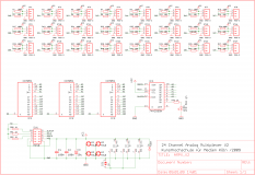
Multiplexer Schematic
Board Layout
Partlist
Amount     Value      Device                Part
 4         1K         1/4 W Resistor        R49, R50,R51,52
 24        10K        1/4 W Resistor        R2, R4, R6, R8, R10, R12, R14, R16, R18, R20, R22, R24, R26,R28, R30, R32, R34, R36, R38, R40, R42, R44, R46, R48
 1         10u        CPOL-EUE2.5-6         C3
 1         74HC595N   74HC595N              IC4
24   opt!  100K       1/4 W Resistor        R1, R3, R5, R7, R9, R11, R13, R15, R17, R19, R21, R23, R25, R27, R29, R31, R33, R35, R37, R39, R41, R43, R45, R47
 2         100n       Cap. 2,54             C1, C2
 1         1N4007     DIODE                 D1
 3         CD4051     4051N or 74HC4051     IC1, IC2, IC3 or 74HC4051
 1         LED 3mm gn LED3MM                LED1
 1         MP10       Header 10pol          SV1
24         PSS-3      Header 3pol           ST1, ST2, ST3, ST4, ST5, ST6, ST7, ST8, ST9, ST10, ST11,ST12,ST13, ST14, ST15, ST16, ST17, ST18, ST19, ST20, ST21,                                 ST22,ST23, ST24
Multiplexer Cascaded to 72 Input Channels
Files
Contact
Martin Nawrath, nawrath@khm.de


